CASE STUDY: DATA CENTER
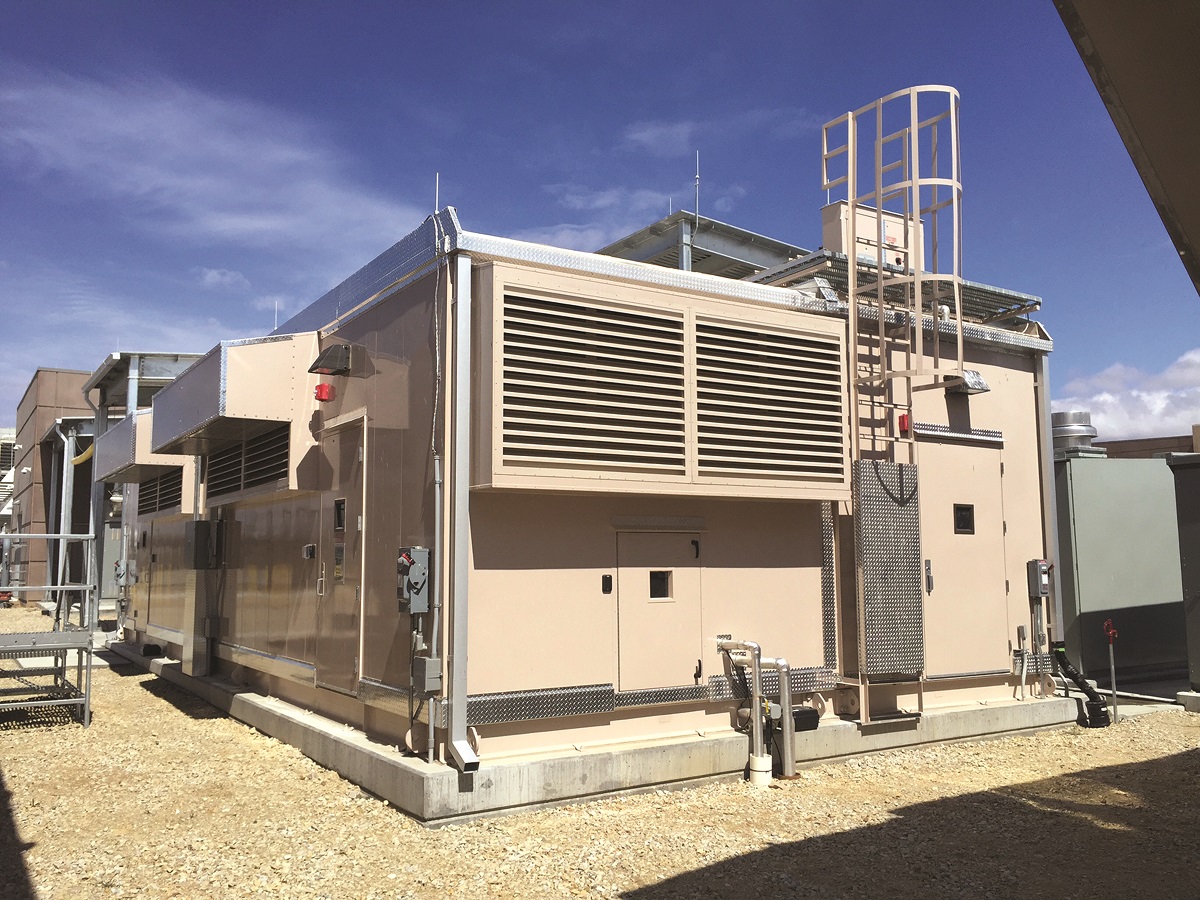
Facility: Power Room Module
Location: Utah
Challenges:
Maintaining a consistent temperature is required to ensure the stability and life DC battery banks.
Solution:
Delivered a fully integrated turnkey modular power room. The HVAC system installed within the DC Module HVAC systems include a DX evaporator and condenser coils.
- Rooftop Air Handling Unit (AHU): Each rooftop air handling unit has the capacity to fully heat and cool the DCM at maximum design conditions all while providing adequate hydrogen dilution.
- Each air handler contains the following components:
- Electric Heating Coil: The electric heating coil is an open element-type heating coil, sized to provide adequate heating during the heating season, including the heating of minimum outside air.
- DX Cooling System: The AHU contains a DX (direct expansion) refrigerant system to provide cooling to the DCM during the cooling season. This system includes a digital scroll compressor, evaporator coil, condenser fan, condenser coil and expansion valve using the environmentally friendly refrigerant R410a.
- Filtration: the air entering the AHU unit is filtered by high efficiency pleated panel filters with a MERV 13 rating to prevent dirt and dust particulates in the air stream being discharged into the DCM.
- Supply Fans: direct-driven backward inclined airfoil blade plenum fans, one per AHU.
- Fan VFD: VFD is connected to the supply fan. The AHU VFD is used as a manual air balancing tool to set fan speed.
- Economizer Dampers: Control dampers for controlling the proportion of return air and outdoor air being supplied to the space.
- Control and Power Panel: Each AHU includes a control and power panel. The panel contains the main mechanical power entry point for the AHU, VFD and motor protectors and the AHU’s PLC controller. The controls panel is responsible for the operation for the entire HVAC system associated with that controller, including the AHU unit itself, its associated condensing unit and the exhaust fan associated with it. Each AHU control panel communicates with the other AHU’s control panel; if a critical failure is registered by one controller, the operation will switch to the other controller’s HVAC system to support the entire HVAC load. All sensors required to automatically maintain the climate within the DCM are terminated back to the AHU control panel. Critical sensors attached to each controller include a backup sensor.
- Exhaust Fan: Axial type fans with VFD-compatible motors. Exhaust fan extracts air out of the module to maintain the DCM room pressure set point, one per HVAC system for a total of two.
- Control sensors and devices.
- The following is a list of sensors and controlled devices used in the HVAC control system for various control or monitoring/alarm purposes. Each of the two HVAC systems in the DCM has its own set of sensors. Refer to P&ID for sensor locations in module.
- Room air temperature sensors.
- Room air hydrogen monitors.
- Mixed air temperature sensors.
- Outside air temperature sensors.
- Filter bank differential pressure switch.
- Room pressure sensors.
- Water detector rope sensors.
- Water leak detectors.
- Supply fans c/w VFD.
- Exhaust fans c/w VFD.
- DX cooling system (compressor, condenser fan, high/low pressure switches, EXV).
- Electric heating coil c/w built-in temperature controls.
- Air flow proving switch.
- R/A damper & actuator.
- O/A damper & actuator.

1.0 System/Equipment Description
The DC Module (DCM) houses two DC battery banks c/w battery chargers and battery selectors. The DCM is comprised of one single module with two (2) HVAC systems each capable of adequately ventilating the module when battery charging is producing hydrogen off-gassing all while maintaining adequate temperature inside the module.
DC Module (DCM) Design:
The DCM has been designed to be an energy efficient controlled environment to maintain the required space temperature. The entire DCM HVAC system had been designed for 2N capacity, with two fully functional HVAC systems that alternate in operation. Both HVAC units include the following major components:
DC Module HVAC Control System Operating Sequences
Normal Operation
The HVAC system maintains the DCM at an allowable pre-defined temperature range (adjustable) through use of the economizer, DX cooling system and electric heating system. The module O/A damper will maintain at least minimum position to ensure that adequate outdoor air is ventilating the module to comply with OSHA regulations. This minimum setting is determined theoretically and confirmed during airflow testing that takes place during module start-up and commissioning. The finalized minimum damper opening is then programmed into the PLC controller.
The DX cooling system and electric heating system in each AHU will activate and operate as necessary to maintain DCM room temperature within the acceptable range. The exhaust fan will modulate to maintain RM Pressure Set point (0.08”). Supply fans operate at a set constant speed. This speed is set at time of commissioning for proper airflow rate.
Each AHU is equipped with a 3-ton nominal DX cooling system capable of covering the entire cooling load requirement of the DCM space. The DX refrigeration cooling system has internal controls and safeties that enable it to operate which are beyond the scope of this document. The operating sequence of the DX cooling system is as follows:
Electric Heating System
Each AHU is equipped with one (1) 6.0 kW electric heating coil capable of servicing the entire heating load requirement of the DCM space. The electric heating coil has internal controls and safeties that enable it to operate. The operating sequence of the electric heating system is as follows:
Emergency Operation – Heating or Cooling
Emergency Operation is commanded ON by the control system when the normal operation of the HVAC system is unable to maintain Emergency Cooling – ON (85°F) or Emergency Heating – ON (55°F). If this occurs, the standby HVAC system is activated and both HVAC systems operate simultaneously. If operating in emergency cooling, both HVAC systems will continue in emergency cooling until the set point Emergency Cooling – OFF (82°F) is reached. If operating in emergency heating, the module HVAC systems will continue in emergency heating until the set point Emergency Heating – OFF (60°F) is reached
Emergency Hydrogen Gas Ventilation Operation
If hydrogen gas levels measured by the H2 monitor in the DCM are above 2%, both AHUs activate. Regardless of room temperature, whenever the H2 gas concentration, detected by the H2 gas monitor by closing its 2% contact signal, is greater than 2% the OA damper opens at 100% and the exhaust fan is forced at full speed until the signal is cleared. The AHU heating and cooling systems will attempt to maintain space temperature, although in some outdoor air temperature conditions the room temperature in the DCM will increase or decrease beyond the normal operating range. Emergency ventilation requires manual reset at the units local control panel start/stop switch or by recycling power to both AHUs. Supply fans in both AHUs operate at the same pre-set speed as during all the time. Both exhaust fans continue to modulate via VFD speed control to maintain RM Pressure Set point (0.08”).
Automatic HVAC System Switchover
General
The DCM control system includes two PLC controllers, one for each HVAC system. Each PLC controller is programmed to operate in a mutually supervisory manner. While one HVAC system is active, the other HVAC system is set to standby. Each HVAC system includes the same sensors and back-up sensors to make two functional and identical HVAC control systems. Any set point changes made to one controller will automatically be communicated to the other controller. Each PLC controller has the capability of communicating with a BMS supervisory system via BACnet/IP communication protocol.
Automatic HVAC System Switchover
AHUs alternate in operation, cycling between each other on a monthly basis.
Each HVAC system controller can sense a critical failure within the control system of the other HVAC system.When such a critical failure occurs within the active HVAC system within the DCM, a forced transfer to the healthy standby HVAC system will occur. The HVAC system that has suffered a critical failure will shut down automatically and the appropriate alarms will be activated. The remaining HVAC system will continue to function to cover 100% of module heating or cooling capacity until, by means of human intervention, the faulty unit is switched OFF then ON by means of the Start/Stop switch or if power is recycled to the HVAC system’s AHU control panel. Normal operation will then be restored. No forced transfer is possible if the pLAN communication between the two HVAC systems is broken. In this situation both systems will activate and operate using their own sensors until pLAN communication between the two PLCs is restored. A pLAN communication lost alarm will be sent to BMS from each HVAC system.
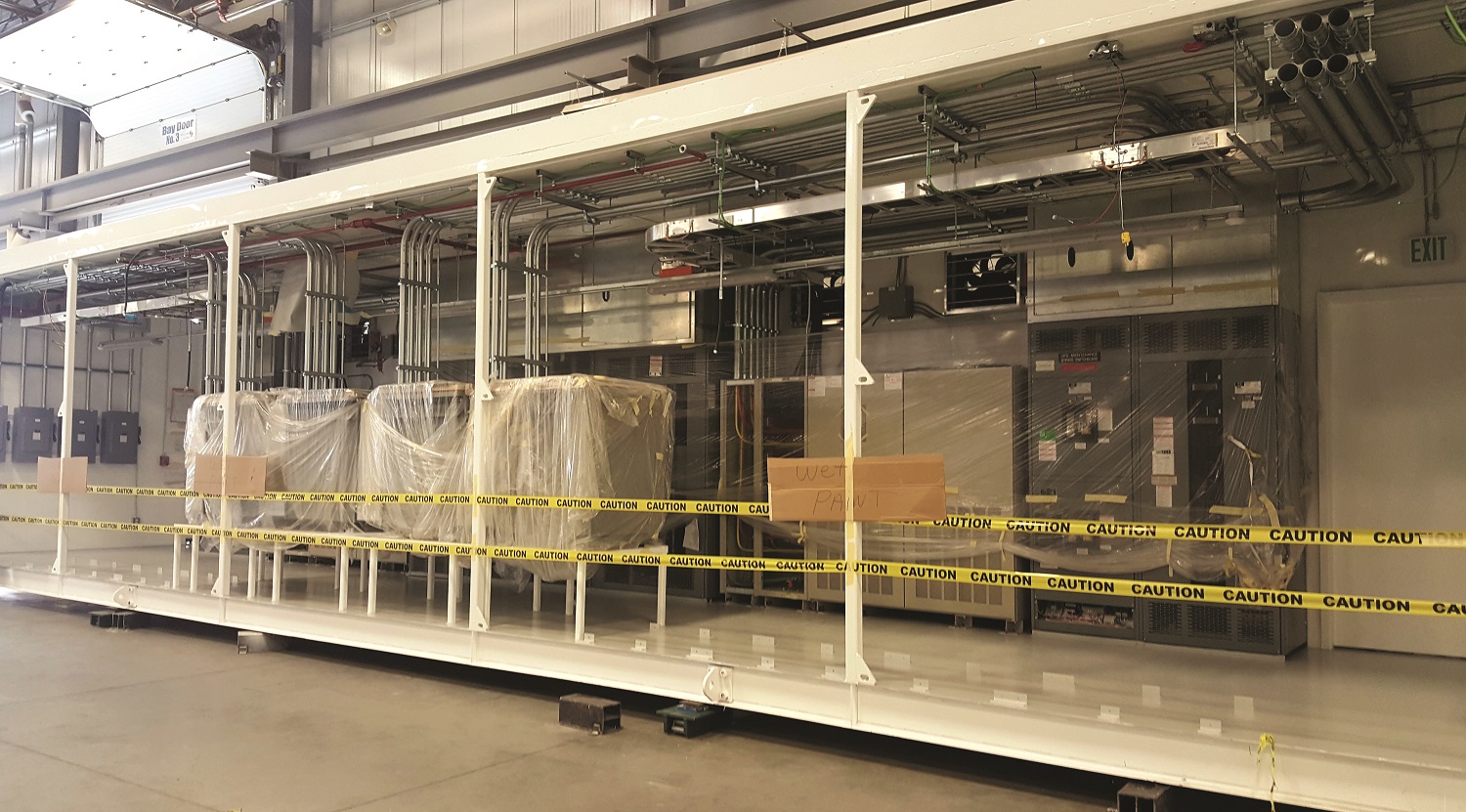
Power Room Modules Summary
The Power Room Module (PRM) provides the enclosure required for the electrical infrastructure comprised of: switchgear, ATS, UPS, batteries, and transformers. The PRM is scalable and can be provided as an integrated section of the FGM DC or as a stand-alone remote enclosure serving the SRM(s) or brick and mortar facility. Integrating vendor agnostic gear provides the end user with the flexibility to select their preferred equipment manufacturers. Cabling is provided in rigid EMT conduit, metal clad, or SO cable with cable tray. The PRM casing and CRACs follows the same construction methods as the SRM. Exhaust systems are positioned at heat producing gear for immediate localized heat rejection from the common plenum. Batteries are strategically located to maintain an optimal constant temperature that ensures no degradation occurs to the batteries due to temperature fluctuations.